DCP test: penetration index, layer thickness and CBR
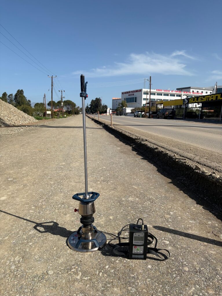
Before a sub-base is placed, or when a road section has failed for no obvious reason, the question is the same: how strong is the material below the surface, and how thick are the layers? The dynamic cone penetrometer (DCP) answers it quickly on site, without taking a sample: a hammer drives a steel cone into the ground, and the penetration per blow gives a strength profile with depth. Below we explain the test, the penetration index (DPI), how CBR is estimated from it and where the method stops being reliable.
The apparatus and the standard
We test to ASTM D6951/D6951M-18(2023), the standard test method for use of the DCP in shallow pavement applications. The apparatus consists of:
- an 8 kg hammer falling 575 mm onto an anvil,
- a 16 mm steel drive rod with a hardened, replaceable 60° cone of 20 mm base diameter, and a millimetre scale,
- an optional 4.6 kg hammer for soft ground. Its penetration per blow is multiplied by 2 to give the 8 kg equivalent; Webster et al. (1992) recommend it for soils with a CBR of about 10 or less.
Our DCP has both hammers: we use the 8 kg hammer as standard and change to the 4.6 kg hammer on soft ground.
ASTM D6951 covers depths of about 1,000 mm with the standard rod. Our extension rods reach about 2 m, but the standard notes that added rods change the mass, inertia and skin friction, so correlations made for the standard set-up are less certain at depth. The DCP is also not the same as dynamic probing to TS EN ISO 22476-2; the results of the two are not interchangeable.
How the test is carried out
- Access: loose material is cleared. Where there is a bound layer (asphalt, concrete or a cement-stabilised base), an access hole is cored or drilled through it first, as ASTM D6951 allows, which is why the DCP pairs well with asphalt coring.
- Seating: the cone is tapped in until its widest part is level with the surface, and the zero reading is taken.
- Driving and readings: the hammer is dropped freely from the handle with the rod kept vertical; the penetration is read after every blow in soft ground, or after a set of blows in stiffer material.
- Stopping: at the target depth or at refusal; Webster et al. (1992) stop when the cone advances less than 25 mm in 10 blows of the 8 kg hammer. If a stone stops the cone or the rod leans, we move a short distance and repeat.
Penetration index and layer thickness
The DPI, in mm per blow, is the penetration between two readings divided by the number of blows between them (×2 for the 4.6 kg hammer). A low DPI means a strong layer, a high DPI a weak one.
Plotted as depth against cumulative blows, a uniform layer gives a roughly straight line; where the slope changes, the material changes. That depth is the layer boundary: it gives the thickness of a base, sub-base or fill and reveals soft zones under a sound-looking surface. Boundaries remain a matter of interpretation, as a wet band or a single stone can blur the break. Where a thickness is critical, we confirm it at a test pit or a core.
Estimating CBR: the ASTM D6951 correlations
The DCP does not measure CBR; it estimates it. The appendix of ASTM D6951 gives three correlations developed by the US Army Corps of Engineers, with DPI in mm/blow for the 8 kg hammer:
| Soil | Correlation | Validity and source |
|---|---|---|
| Most soils | CBR = 292 / DPI1.12 | All soils except CL soils with CBR below 10 and CH soils (Webster et al., 1992) |
| Low-plasticity clay (CL) | CBR = 1 / (0.017019 × DPI)2 | Only where CBR is below 10, i.e. DPI above about 19 mm/blow (Webster, Brown and Porter, 1994) |
| High-plasticity clay (CH) | CBR = 1 / (0.002871 × DPI) | CH soils (Webster, Brown and Porter, 1994) |
CL and CH are clay groups of the Unified Soil Classification System (ASTM D2487-17(2025)), with a liquid limit below 50 and of 50 or more respectively; we determine the liquid limit in the laboratory to TS EN ISO 17892-12:2018+A2:2022. The choice matters: for a DPI of 40 mm/blow, the general, CL and CH equations give a CBR of about 5, 2 and 9.
The correlations have clear limits:
- They are empirical fits to field data from US military roads and airfields, with CBR values of roughly 3 to 100 behind the general equation (Webster et al., 1992). They were not derived from Cyprus soils and are not universally valid.
- They apply to the 8 kg hammer (or the corrected 4.6 kg result) with the standard cone.
- ASTM D6951 notes that a field CBR estimated this way will not normally agree with a soaked laboratory CBR.
- In high-plasticity clays, soil sticking to the rod can make strength appear to rise with depth; Webster et al. (1992) treat readings in such clays as reliable to about 300 mm.
- Readings scatter, so we report a representative value per layer and always name the equation used.
Where the DCP is useful
- subgrade checks before the sub-base is placed,
- trench backfill, to see whether the lower lifts are as well compacted as the top,
- pavement failures: testing a failed and a sound section through core holes to find the weak or thin layer,
- fill under ground-floor slabs and around foundations, where a test pit would be disruptive,
- the early stage of a road site investigation, alongside test pits and laboratory classification.
Limits of the method
- Coarse material: ASTM D6951 excludes granular materials with a significant share of aggregate larger than 50 mm; stones deflect or stop the cone.
- Cemented layers: highly stabilised or cemented materials, or a hard calcrete crust, stop the cone and have to be cored through.
- Water content: clayey soils read weaker after rain and stronger as they dry, so compare results taken in similar conditions.
- Surface: the top of a loose granular layer is unconfined and reads weaker than the layer as a whole.
- Not a density test: ASTM D6951 allows density to be inferred only through a correlation built for that specific material. Where the specification asks for a degree of compaction, a sand cone test is needed.
- Not a laboratory CBR: the estimate does not replace a CBR test to TS EN 13286-47:2021 where one is specified.
The acceptable DPI or CBR for a layer is set by the project specification and the pavement or geotechnical engineer. We report the data and the correlation used, not a design.
DCP, LWD or sand cone?
| Test | What it answers | Standard |
|---|---|---|
| DCP | Strength profile with depth, layer thicknesses, estimated CBR | ASTM D6951/D6951M-18(2023) |
| LWD (Zorn ZFG 3.1) | Evd stiffness of the layer system at the surface, in about two minutes per point | ASTM E2835-21(2026) |
| Sand cone | In-place dry density and degree of compaction against the Proctor reference | ASTM D1556/D1556M-24, TS 13872:2019+T1:2026 |
On a road the three work together: the LWD covers many points on each layer, the sand cone gives the specified degree of compaction, and the DCP shows what lies beneath. See our guides on LWD compaction control and the Evd value, the sand cone test and degree of compaction and Proctor, CBR and water content tests.
How we can help
We test with both hammers as part of our site investigation and DCP testing service, core bound layers where needed, and classify samples in our soil laboratory when the CBR equation depends on the soil type. Our report gives:
- the location of each point (plan or coordinates) and its start depth (surface or below a core),
- the hammer used and the raw readings,
- plots of depth against cumulative blows and of DPI against depth,
- layer boundaries, the DPI of each layer and the estimated CBR with the equation named.
Send us the drawings, the layers to be checked and the specification through our contact page.
Frequently asked questions
Can the DCP replace a laboratory CBR test?
No. It gives a field estimate from a correlation, which ASTM D6951 notes will not normally agree with a soaked laboratory CBR. Where the specification sets a CBR for a material, the laboratory test is still needed.
Can you test under asphalt or a concrete slab?
Yes, through a cored or drilled access hole, starting on the material beneath. The core also gives the thickness of the bound layer.
How deep does the test go?
About 1 m with the standard rod and about 2 m with extension rods, where rod friction makes the readings less certain. For foundations or greater depths, boreholes are the right tool; see our geotechnical drilling page.